Jump to:
Case Study: Steam Turbine Casing Repair
Gas compressor turbines are key equipment in the oil and gas industry, power plants, and many industrial applications. This refurbishment project was initially prompted by a routine inspection of the turbine’s inside housing using an endoscope — Fig. 1. The inspection was conducted six months ahead of a scheduled plant shutdown to determine whether repair work was necessary.
Previous inspections and overhauls had already revealed gradual erosion-induced wear of the inner wall surface, which was now very advanced in some areas. Notably, the section around the gas outlet nozzle was most affected. A critical approach to the calculated minimum wall thickness was localized at some spots. If these minimums were not met, the turbine would need to be taken out of operation immediately, and the entire production plant would have to be shut down.
Partial deposition welding, primarily in areas where the erosion was most advanced (Fig. 2), was considered as a repair method to prevent the worst-case scenario of an imminent plant shutdown. Based on an original wall thickness of 30 mm, the wear profile in the selected repair areas was between a minimum eroded depth of 4 mm and a maximum of 11 mm.
Welding Process Selection
Instead of selecting a classic arc welding process, which would have required additional work, pulsed laser beam welding (PLBW) technology was used due to its specific benefits. The PLBW repair was carried out by DSI Laser Service (Thailand). The choice of this process was directly connected to the tight schedule because it does not require any reworking related to the base material during or after the welding process. The total plant shutdown was scheduled for 18 days; five days were planned for the repair, including the necessary preparations and an extensive quality control plan.
Some of the advantages of PLBW are faster welding start times (under 25 ms), no pre- or postheat treatment at room temperature, a very thin (about 0.2 mm) heat-affected zone (HAZ), no critical microstructure changes, no coarse grain formation (which weakens the metal structure), very low heat input (because of welding with pulsed light and its speed, there’s no HAZ of the base material), and almost no distortion.
The fusion line showed that the base material and the filler material were fully joined together. This strong bond made the final material almost as strong as the original base material even without needing extra heat treatment afterward.
PLBW Qualification Procedures
To carry out the work, the welding repairs were preceded by extensive qualification procedures using welding procedure specifications (WPSs) and procedure qualification records (PQRs). These were used to qualify the PLBW process and the welder, who also operated the machine. The qualification and certification procedures were carried out by DSI Thailand Laser Welding Academy in cooperation with the authorized third party, KINGWELD (Bangkok).
The WPS and PQR followed AWS C7.4/C7.4M:2017, Process Specification Operator Qualification for Laser Beam Welding, and AWS D14.6/14.6M:2012, Specification for Welding of Rotating Elements of Equipment. The latter was used due to the customer’s special request, even though the component to be welded was not the rotating turbine rotor but only its static housing.
Repair Preparation
The repair procedure entailed determining the actual housing dimensions and considering the form and position tolerances, particularly the flanges and the alignment of reference surfaces.
Planning for PLBW included mechanical surface preparation of the designated welding areas by hand grinding.
Measuring equipment (i.e., dial gauges) was set up for continuous distortion monitoring during the ongoing welding process — Fig. 3. Four dial gauges, staggered by 90 deg, were installed around the turbine exhaust flange (one at the outer edge and one at the lower edge).
PLBW Process
The deposition of designated areas ranged between 4 and 11 mm. For the base material, A216 WCA / ASTM 216, the selected filler material was DSI M NICR625 (Inconel 625), with a diameter of 1.2 mm.
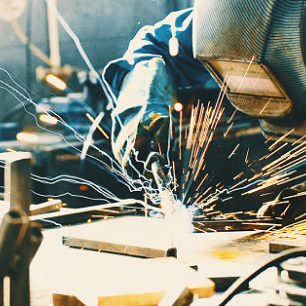
Welding was done with an AL Flak 1200 F fiber laser machine, and the operator used a joystick to control welding direction movements. At the same time, the filler metal was fed in manually. At 1200 watts of pulsed laser power, the molten pool had a diameter of 5.2 mm — Fig. 4.
Inspection and Quality Control
The intermediate quality control procedures during welding included visual testing (VT) and liquid penetrant testing (PT) after every 3 mm of deposition. Continuous distortion control was monitored via dial gauges (see Fig. 3). The maximum distortion observed was 0.025 mm.
Final inspection after welding included VT, PT, and magnetic particle testing — Fig. 5. Additionally, radiographic testing and ultrasonic testing were performed — Fig. 6.
Conclusion
This case provided a noteworthy example of the benefits of PLBW, which achieved complete metallurgical bonding without any welding discontinuities or defects (cracks, incomplete fusion, or porosity) while providing benefits that conventional arc welding methods typically cannot — Fig 7.
The comprehensive inspection and quality control plan provided thorough verification and satisfactory results.
STEPHAN THIEMONDS (thiemonds@dsilaser.com) is the welding department manager at DSI Laser Service (Thailand) Co. Ltd. and the principal of DSI Thailand Laser-Welding-Academy, Chonburi, Thailand. He is an International Institute of Welding (IIW) International Welding Specialist (IWS).

Community and Events

Weld Wednesday
Our monthly podcast tackles a variety of welding topics for listeners in any position
within the industry.