Inspection Trends
Jump to:
Autonomous Friction Stir Welding Inspection in Aerospace Production
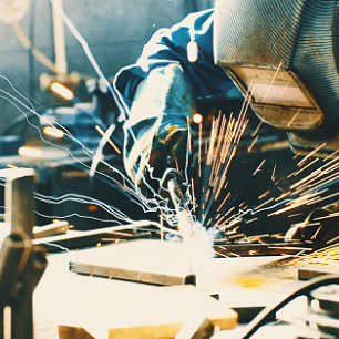
The friction stir welding (FSW) process was developed to join materials that are difficult to fusion weld, such as aluminum alloys — Fig. 1. The weld quality is very high, and the material structure is uniform. It is commonly used in aerospace manufacturing where high-strength welds are required for large structures, such as rocket propulsion fuel tanks.
Friction stir welding is a process unlike most others in that no liquid-state weld pool exists. As such, the potential defects in the weld are quite different. The defects present in such welds are typically incomplete joint penetration, wormholes, porosity, kissing bonds, and root toe defects. Furthermore, because of the nature of the weld process, defects can be orientated in any direction.
The best method for inspecting friction stir welds is phased array ultrasonic testing (PAUT) using water-coupled wedges. The increased number of zones covered by the phased array ultrasound provides accurate defect detection and location.
Typical FSW Flaws
Some typical flaws that inspectors need to look for in friction stir welds include incomplete joint penetration, kissing bonds (entrapped oxide), voids and tunnels (Fig. 2), wormholes, and hooks. These flaws can be oriented in the weld’s longitudinal and transverse directions.
Recommended PAUT Technique for FSW
Phased array probes can be used to inspect the entire weld volume with a single-pass scan. High speed, accuracy, and versatility make phased array a popular technique for FSW inspection.
For example, to inspect for longitudinal flaws, two 10-MHz, 64-element transducers with 45-deg shear wave angles are used. The first probe’s orientation is skewed 90 deg, and the second is skewed 270 deg from the weld center line.
To inspect for transverse flaws, two 10-MHz, 128-element transducers with 45-deg shear wave angles are used. These probes are mounted laterally to cover the weld zone completely, skewing one probe at 0 deg and the second at 180 deg from the weld center line.
Water wedges are the most efficient way to couple and contour along the inspected component. These closed-chamber boxes hold the sensors at precise angles, efficiently couple to the part, and recuperate water for minimal water loss.
The phased array probes and wedges can be mounted on an inspection head that positions the probe-wedge assemblies for full weld coverage. Figure 3 shows how each probe can be precisely mounted to create a single-pass inspection. The inspection head is designed to provide optimal and uniform pressure across all the sensors; it is compact to access tight areas and retracts the sensors to avoid areas that are not a target for testing.
Detection Capability
Using the phased array probe configuration shown in Fig. 3, small flaws with a high single-to-noise ratio (SNR) can be detected. Figure 4 shows the scan results for a typical calibration standard for FSW inspection. On the most minor flaws (0.13 mm [0.005 in.] deep × 0.25 mm [0.009 in.] wide × 1.27 mm [0.05 in.] long), a 14-dB SNR can be achieved. On the most significant flaws (0.51 mm [0.02 in.] deep × 0.25 mm [0.009 in.] wide × 2.16 mm [0.085 in.] long), an SNR of up to 33 dB is achieved.
Automated FSW Inspection
Although phased array is a highly efficient inspection technique, automation is required to provide positioning precision, remove operator dependency, and maintain production speed requirements for manufacturing. Using stationary collaborative robots, shown in Fig. 5, results in a workflow that efficiently calibrates before and after inspection, accurately places sensors on inspection components, and manages water coupling and recuperation. Such systems enable you to achieve the FSW inspection results shown in Fig. 4 at 75 mm (2.95 in.) per second or higher speeds.
Factory 4.0 Inspection System
Factories of the future require dynamic use of floor space to optimize resources and production workflow. Like the one shown in Fig. 5, stationary collaborative robot inspection systems are ideal tools when production environments allow for dedicated space. However, through innovations with automated guided vehicles (AGVs), it is now possible to combine the benefits of phased array and collaborative robots with the portability of AGVs. Figure 6 shows how all these technologies can be combined. Using this method, the inspection can be transported to the components rather than the components to the inspection station. This also expands the possibility for aerospace manufacturers to harness the power of phased array and automation for friction stir welding inspection.
JEFFREY WELLS (jeffrey.wells@evidentscientific.com) is systems and integrations sales manager of the Americas at Evident Industrial, Waltham, Mass.


